

Cox Medallion .051 NFFS Special
|
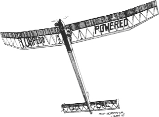
Flying the Lucky Lindy in NFFS Nostalgia Class A-B by Bob Beecroft, Fallbrook, California, USA
See bottom for how to properly do those Lindy tips!
The following in italics is from Sergio Montes, editor of Free Flight Quarterly, an outstanding Australian newsletter. Contact Sergio here: montes@iinet.net.au
The Lucky Lindy has performed well in this category, and Bob Beecroft is one of the most successful contenders. Here he shares some of the trimming and flying mods that he has used in his Lucky Lindys. He also is a great engine tuner, and has much to say in tuning the engines for these ships. Class A allows up to .19 cu.inch displacement, and Bob has found in the Veco Series 100 .19 engine a very potent and rather easily found replacement for the OS Max 15 that Conover used. Ed.
Updated here in December 2006. The text below appears in the 1st Quarter issue of Free Flight Digest, Australia.
Plans: Beecroft’s Lucky Lindy has been campaigned from 1990 to date. The Jim O’Reilly plans were done at my request, and include incidence, CG, warps, etc. found and proven to work very well in over a decade of campaigning this model.. References are for these plans drawn to my specifications.
AIRPLANE MODEL PLANS - Beecroft's FAI Lucky Lindy FAI and also a 659 inch (Projected) version for strong running .29's available here:
Jim O’Reilly, 4760 N. Battin, Wichita, KS 67220 Fax: (316) 744-0856 Phone: (316) 744-0856 E-mail: KSFreeflit@aol.com Website: jimoreillymodelplans.com
The Jim O'Reilly plans are a composite of the original MkII plans (dated 11/1957, drawn by Dottie Conover, published in the March 1958 American Modeler) with structural and other changes that Bob Beecroft had Jim draw into the plans.
Engine offsets: Use 3° 0' Left thrust and 2° 45' Down thrust. It is certainly better to build these in to start, rather than the cobby way shown on the '58 American Modelerplan. No side thrust shown on those plans, but the 3° Left sure makes it VTO straight.
Stab: Set at 90° to fuselage CL . Tilt - 7/16" difference left to right, right side high for right glide. Less tilt better for more calm air duration / big fields. I am using 1/4” now (2003 to date). Keep it light!
Wing: Center section: Flat. Left main panel: Flat. Right main: 7/32-1/4" Wash-in Left tip: 1/8" Wash-out. Right tip: 1/16" Wash-out. Additionally, I recommend aileron trim tab on the wing main panel as shown: screw-adjusting a great idea. See note under Fin Offsets regarding mounting.
Fuselage: As per O’Reilly plan outline. Sides, top and bottom - I recommend splicing the lengths using long scarf joints. Use nice firm wood from the firewall to the rear of the pylon area, nice light wood for the tail boom. I use a piece of 6000 strand carbon-fibre tow Cyanoed in place (inside) top and bottom of each fuselage side. I do this by placing the CF down straight, using thin Cyano a drop or two at a time onto it. Watch it wick in and along a length, then quickly cover with waxed paper and rub it down hard. Then do the next length till it reaches the end. I double it up at nose, running a second 6000 strand piece at the top and bottom of the fuse sides to about 3" past the rear of the pylon. About a 6" piece overlaps the stab LE area, lapping about 3" either side of the stab platform top and bottom again. Once this is done, the fuselage is built in the normal box body manner. 2018: Try using 2.5mm hollow square CF tube per George Voss. I think this is a great idea for sizes bigger than Half A's and my new Nos Gas fleet will be built this way. See andrihenri-0 (or O) on eBay. Great price and selection, and extraordinarily good shipping rates.
Additionally, I like to use about 3 layers of 3-ounce glass S-cloth around the nose. One a couple of inches back from the firewall, the second to about the mid-point of the pylon, and the third to a point a couple of inches past the pylon. Make that fuselage straight! That CF on the inside makes that old box of balsa really really strong, and the reinforced front end will last through years and years of handling!!
CG Position: As per O’Reilly plan. The more rearward position shown (5½") for high power engines (K&B GreenHead .19-.23) per Conover's original plan. However, my experience with a very hot Veco .19: the CG at 5¼" behind the LE seems to work well. Trimmed for a larger glide circle, the CG will need to move a bit, so keep the tail light. Move the pylon to achieve the initial CG, leaving it just a little nose heavy to allow for dings and repairs that come along most always behind the CG! Mine has the front of the pylon shoved forward to 1¼" behind the firewall with a bit of lead in the tail. Better to have to add here than anywhere else. It is easy to take out to make minor glide trim adjustments.
Fin offsets: Make every effort to see that everything is dead-straight (or at 90° to the fuse CL like the wing and stab). Use an engineer's square to ensure the tip fins are really 90° to the stab span. Mine flies with the tiny tab as shown on the O’Reilly plan. It is either dead-straight or with a tiny bit of right screwed in (1/32” is a lot). For Cat III's short motor runs and fly-off's, the tab goes a bit right to get a better transition from slower speeds attained. Longer runs, use less tab and a straighter climb where there is sufficient speed to go over the top to gain altitude through recovery to glide. The tab is sensitive, like Conover notes. I use a 1-72 screw on a post on the center fin only for adjustments. Try mounting the tab using .020 music wire acting as both hinge and a torsion bar for spring tension on the tab. Works great.
Incidence: As per O’Reilly plan, both wing and tail. Leave a little room under the stab TE for positive incidence adjustments a 1/32" or so. There is a coincident small amount of positive stab incidence that needs to be cranked in as the power goes up and the CG moves back. DT hammer with screw-adjustment highly recommended. Mechanical or electronic timer activation is a wonderful improvement. Both the Black Magic electronic timer by Roger Morrell and Rod Mogle’s electronic timer have a fervent following, and for good reason. Of course the trusty old Seelig mechanical timer is great, too. Any of these is a wonderful improvement over a Tatone and a fuse. (2018: My new fleet will be using timers and GPS retrieval systems from Massimo at FFelectronics.com. I have his Seelig-style F1C timers and new GPS trackers. Both wonderful. RKB)
Dihedral: As per the O’Reilly plan.
Spars: Lots of great ways to build them, no question. My spars consist of a spruce-balsa-spruce sandwich. Details can be seen here: http://albums.photo.epson.com/j/AlbumIndex?u=4184262&a=31534433&f= (Dead site---I need to find these photos and update. Sorry...)
|
||
 |
|
|
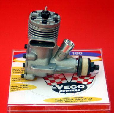 |
Make your Lucky Lindy really Rock and Roll!! See pages on motors: Motor Stuff, and The Series 100 Veco 100 Engines.
|
|
 |
Wing tips on Conover's model (here, his Mk I entered in the '58 WC). This is the RIGHT way to do LL tips! Photo: Ted Hidinger
|
|
